Preload and Load Capacitiy
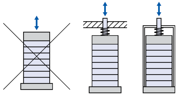
The tensile strengths of brittle piezoceramic and single-crystal actuators are relatively low, with values in the range of 5 to 10 MPa. It is therefore recommended to mechanically preload the actuators in the installation. The preload should be selected as low as possible. According to experience, 15 MPa is sufficient to compensate for >> Dynamic Forces; in the case of a constant load, 30 MPa should not be exceeded.
Lateral forces primarily cause shearing stresses in short actuators. In longer actuators with a larger aspect ratio, bending stresses are additionally generated. The sum of both loads yield the maximum lateral load capacities, which for >> PICA Shear Actuators are given in the data sheet. These values can be transfered to actuators with a similar geometry. However, it is normally recommended to protect the actuators against lateral forces by using guidings.
Limitations of the Preload
The actuator begins to mechanically depolarize already at a few 10 MPa. A large-signal control repolarizes the actuator; on the one hand, this causes the induced displacement to increase but on the other hand, the effective capacity and loss values increase as well, which is detrimental to the lifetime of the component.
A pressure preload also partially generates >> Tensile Stress. For this reason, when very high preloads are used, the tensile strength can locally be exceeded. The amount of the possible preload is not determined by the strength of the ceramic material. Piezo actuators attain compressive strengths of more than 250 MPa.
The actuator stiffness kA is an important parameter for calculating force generation, resonant frequency, and system behavior. Piezoceramic stack actuators are characterized by very high stiffness values of up to several hundred newtons per micrometer.
The following equation is used for calculation:

Bending actuators, however, have stiffnesses of a few newtons per millimeter, lower by several orders of magnitude. In addition to the geometry, the actuator stiffness also depends on the effective elasticity module E*.
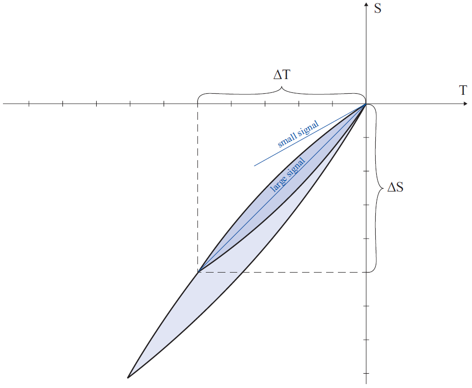
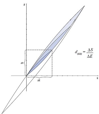
Because of the mechanical depolarization processes, the shape of the stress/strain curves (fig. 1) is similarly nonlinear and subject to hysteresis as are the electromechanical curves (fig. 2). In addition, the shape of the curve depends on the respective electrical control conditions, the drive frequency, and the mechanical preload so that values in a range from 25 to 60 GPa can be measured. As a consequence, it is difficult to define a generally valid stiffness value.
kA | Actuator stiffness |
E* | Effective modulus of elasticity: Linear increase in a stress/strain curve of a test speciment or actuator made of the corresponding piezoceramic material |
A | Actuator cross-sectional area |
l | Actuator length |
S | Mechanical strain |
T | Mechanical stress |
The stiffness considerably increases when the actuator is electrically operated at a
high impedance, as is the case with charge-control amplifiers. When a mechanical load is applied, a charge is generated that cannot flow off due to the high impedance and therefore generates a strong opposing field which increases the stiffness.
For specifying piezo actuators, the quasistatic large-signal stiffness is determined with simultaneous control with a high field strength or voltage and low mechanical preload. This serves for taking into account an unfavorable operating case, i.e., the actual actuator stiffness in an application is often higher.
The adhesive layers in the PICA actuators reduce the stiffness only slightly. By using optimized technologies, the adhesive gaps are only a few micrometers high so that the large-signal stiffness is only approx. 10 to 20 % lower than that of multilayer actuators without adhesive layers. The actuator design has a much stronger influence on the total stiffness, e.g., spherical end pieces with a relatively flexible point contact to the opposite face.
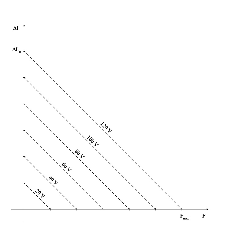
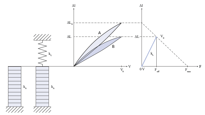
The generation of force or displacement in the piezo actuator can best be understood from the working graph (fig. 3). Each curve is determined by two values, the nominal displacement and the blocking force.
Nominal Displacement
The nominal displacement ΔL0 is specified in the technical data of an actuator. To determine this value, the actuator is operated freely, i.e. without a spring preload, so that no force has to be generated during displacement. After the corresponding voltage has been applied, the displacement is measured.
Blocking force
The blocking force Fmax is the maximum force generated by the actuator. This force is achieved when the displacement of the actuator is completely blocked, i.e. it works against a load with an infinitely high stiffness. Since such a stiffness does not exist in reality, the blocking force is measured as follows: The actuator length before operation is recorded. The actuator is displaced without a load to the nominal displacement and then pushed back to the initial position with an increasing external force. The force required for this is the blocking force.
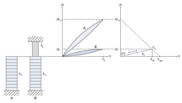
If the piezo actuator works against a spring force, its induced displacement decreases because a counterforce builds up when the spring compresses. In most applications of piezo actuators, the effective stiffness of the load kL is considerably less than the actuator stiffness kA. The resulting displacement ΔL is therefore close to the nominal displacement ΔL0:
The careful introduction of force is especially important in this load case, since large mechanical loads arise in the actuator. In order to achieve a long lifetime, it is imperative to avoid local tensile stresses.
Feff | Effective force |
Fmax | Blocking force |
kL | Load stiffness |
kA | Actuator stiffness |
ΔL0 | Nominal displacement |
ΔL | Displacement |
V | Operating voltage |
V0 | Nominal voltage |
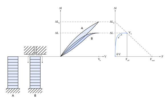
As an example of a load case in which a nonlinear working curve arises, a valve control is sketched in fig. 6. The beginning of the displacement corresponds to operation without a load. A stronger opposing force acts near the valve closure as a result of the fluid flow. When the valve seat is reached, the displacement is almost completely blocked so that only the force increases.
Feff | Effective force |
Fmax | Blocking force |
kL | Load stiffness |
kA | Actuator stiffness |
ΔL0 | Nominal displacement |
ΔL | Displacement |
V | Operating voltage |
V0 | Nominal voltage |
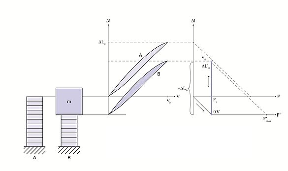
If a mass is applied to the actuator, the weight force FV causes a compression of the actuator. The zero position at the beginning of the subsequent drive signal shifts along the stiffness curve of the actuator. No additional force occurs during the subsequent drive signal change so that the working curve approximately corresponds to the course without preload (fig. 7).
An example of such an application is damping the oscillations of a machine with a great mass.
Feff | Effective force |
Fmax | Blocking force |
kL | Load stiffness |
kA | Actuator stiffness |
ΔL0 | Nominal displacement |
ΔL | Displacement |
V | Operating voltage |
V0 | Nominal voltage |
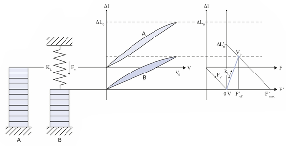
If the mechanical preload is applied by a relatively soft spring inside a case, the same shift takes place on the stiffness curve as when a mass is applied (fig. 8). With a drive voltage applied, however, the actuator generates a small additional force and the displacement decreases somewhat in relation to the case without load due to the preload spring. The stiffness of the preload spring should therefore be at least one order of magnitude lower than that of the actuator.
In longitudinal stack actuators, the actuator length is the determining variable for the displacement ΔL0. At nominal field strengths of 2 kV/mm, displacements of 0.10 to 0.15 % of the length are attainable. The cross-sectional area determines the blocking force Fmax. Approximately 30 N/mm² can be achieved here.
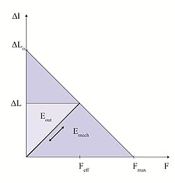
Accordingly, the determining parameter for the mechanical energy Emech = (Δ L0 Fmax)/2 to be attained is the actuator volume.
The energy amount Emech, that is converted from electrical into mechanical energy when an actuator is operated, corresponds to the area underneath the curve in fig. 9. However, only a fraction Eout of this total amount can be transferred to the mechanical load. The mechanical system is energetically optimized when the area reaches its maximum. This case occurs when the load stiffness and the actuator stiffness are equal. The light blue area in the working graph corresponds to this amount. A longitudinal piezo actuator can perform approx. 2 to 5 mJ/cm³ of mechanical work and a bending actuator achieves around 10 times lower values.
Efficiency and Energy Balance of a Piezo Actuator System
The calculation and optimization of the total efficiency of a piezo actuator system depends on the efficiency of the amplifier electronics, the electromechanical conversion, the mechanical energy transfer, and the possible energy recovery. The majority of electrical and mechanical energies are basically reactive energies that can be recovered minus the losses, e.g., from heat generation. This makes it possible to construct very efficient piezo systems, especially for dynamic applications.
Ask an engineer!
Quickly receive an answer to your question by email or phone from a local PI Ceramic sales engineer.
